Showing posts with label Testing components. Show all posts
Sunday, November 1, 2009

How to test a diode

Diodes are one of the components that can be tested very easily.Ordinary diodes as wells as Zener diodes can be checked by using a multimeter. While testing a diode the forward conducting mode and reverse blocking mode has to be tested separately.

Testing ordinary diode using a digital multimeter.
To check an ordinary silicon diode using a digital multimeter, put the multimeter selector switch in the diode check mode. Connect the positive lead of multimeter to the anode and negative lead to cathode of the diode. If multimeter displays a voltage between 0.6 to 0.7, we can assume that the diode is healthy. This is the test for checking the forward conduction mode of diode. The displayed value is actually the potential barrier of the silicon diode and its value ranges from 0.6 to 0.7 volts depending on the temperature.

Now connect the positive lead of multimeter to the cathode and negative lead to the anode. If the multimeter shows an infinite reading (over range), we can assume that the diode is healthy. This is the test for checking the reverse blocking mode of the diode.
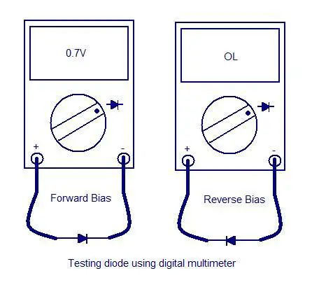
testing-diode-using-digital-multimeter

For testing Germanium diodes, the procedure is same but the display will be between 0.25 to 0.3 V to indicate a healthy condition in the forward biased mode. The potential barrier for Germanium diode is between 0.25 and 0.3V.When reverse biased the multimeter will show an infinite reading (over range) to indicate healthy condition.

Testing ordinary diode using analog multimeter.
To check an ordinary Silicon diode using an analogue multimeter, put the multimeter selector switch in a low resistance position (say 1K).Connect the positive lead of multimeter to anode of the diode and negative lead of multimeter to cathode of the diode. If meter shows a low resistance reading, we can assume that the diode is healthy. This is the test for checking forward biased mode of the diode.

Now put the multimeter selector switch in a high resistance position (say 100K).Connect the positive lead of multimeter to cathode of the diode and negative lead to anode of the diode. If the meter shows an infinite reading, we can assume that the diode is healthy. This is the test for checking the reverse blocking mode of the diode. The meter shows infinite or very high resistance reading because a reverse biased diode has a very high resistance (usually in the range of hundreds of K Ohms).
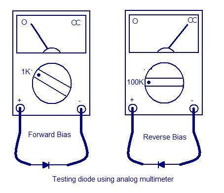
testing-diode-using-analog-multimeter


Testing Zener diode.
The forward characteristics of a Zener diode is similar to an ordinary diode.So the methods used for testing forward conducting mode of any ordinary diode is applicable to the Zener diode too.But in reverse mode, the reverse breakdown voltage has great significance and it has to be specifically tested.For example a 5.3V Zener diode must start conducting only when the applied reverse voltage just exceeds 5.3V.The reverse bias mode of Zener diode can be easily tested by using the circuit given below.The resistance R1 can be typically 100Ohms.The multimeter must be in voltage mode.Now slowly increase the output of variable power supply and at the same time observe the voltage shown in the multimeter. The multimeter display increases along with the increase in power supply voltage until the breakdown voltage. Beyond that the multimeter reading stays put despite of the power supply voltage. This is because the Zener diode is now in breakdown region and the voltage across it will remain constant irrespective of the increase in supply voltage and this constant voltage will be equal to the breakdown voltage. If the reading of multimeter in this instant is equal to the breakdown voltage specified by the manufacturer, we can assume that the Zener diode is healthy.
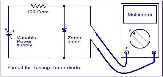
circuit-for-testing-zener-diode

While carrying out this test, remember not to exceed the input excitation voltage to a point that forces the Zener diode to dissipate more power than it can safely handle. Typically current through the diode should not be allowed to exceed more than 10mA.

Testing triac using a multimeter.
A multimeter can be used to test the health of a triac. First put the multimeter selector switch in a high resistance mode (say 100K), then connect the positive lead of multimeter to the MT1 terminal of triac and negative lead to the MT2 terminal of triac (there is no problem if you reverse the connection).The multimeter will show a high resistance reading (open circuit).Now put the selector switch to a low resistance mode, connect the MT1 and gate to positive lead and MT2 to negative lead. The multimeter will now show a low resistance reading (indicating the switch ON).If the above tests are positive then we can assume that the triac is healthy. Anyway this test is not applicable triacs that require high gate voltage and current for triggering.

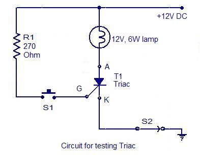
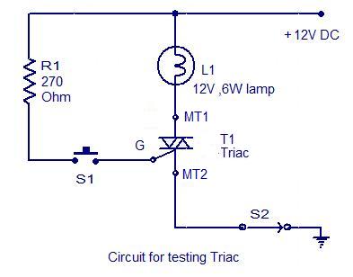
Circuit for testing a triac.
This is another approach for testing a triac. Almost all type of triacs can be tested using this circuit. This circuit is nothing but a simple arrangement to demonstrate the elementary action of a triac. Connect triac to the circuit as shown in circuit diagram and switch S2 ON. The lamp must not glow. Now press the push button switch S1.The lamp must glow indicating the switching ON of triac. When you release the push button, you can see the lamp extinguishing. If the above tests are positive you can assume that the triac is healthy.

circuit-for-testing-triac

Testing SCR using a multimeter.
A multimeter can be used to test SCRs quite effectively. The first procedure is to check the diode action between the gate and cathode terminals of the SCR. This test is just like what you have done in the case of testing a silicon diode (see testing a silicon diode).

Now put the multimeter selector switch in a high resistance position. Connect the positive lead of multimeter to the anode of SCR and negative lead to the cathode. The multimeter will show an open circuit. Now reverse the connections and the multimeter will again show an open circuit.

Then connect the anode and gate terminals of the SCR to the positive lead of multimeter and cathode to the negative lead. The multimeter will show a low resistance indicating the switch ON of SCR. Now carefully remove the gate terminal from the anode and again the multimeter will show a low resistance reading indicating the latching condition. Here the multimeter battery supplies the holding current for the triac. If all of the above tests are positive we can assume the SCR to be working fine.

Circuit for testing SCR.

This is another method for testing an SCR. Almost all types of SCR can be checked using this circuit. The circuit is just a simple arrangement for demonstrating the basic switching action of an SCR. Connect the SCR to the circuit as shown in diagram and switch S2 ON. The lamp must not glow. Now press the push button switch S1 ON and you can see the lamp glowing indicating the switch ON of SCR. The lamp will remain ON even if the push button S1 is released (indicates the latching).If the above checks are positive then we can conclude that the SCR is fine.

circuit-for-testing-scr

UJT (Uni junction transistor) can be easily tested by using a digital multimeter.The three steps for testing the health of a UJT are as follows.

1. Measuring the resistance between B1 and B2 terminals.

Set your digital multimeter in resistance mode.Connect the positive lead of multimeter to the B1 terminal and negative lead to the B2 terminal.The multimeter will show a high resistance ( around 4 to 10K ). Now connect the positive lead to B2 terminal and negative lead to B1 terminal.Again the multimeter will show a high resistance (around 4 to 10K ).Also both the readings will be almost same.

measuring-resistance-between-b1-and-b2

2.Reverse biasing the emitter junction.

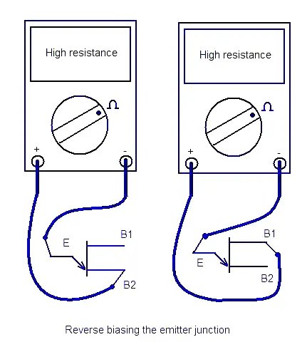
Set the digital multimeter in resistance mode.Connect negative lead of the multimeter to the emitter and positive lead to the B1.The multimeter will show a high resistance (around 100’s of K’s).Now connect the negative lead once again to the emitter and positive lead to B2.Again the meter will show a high resistance.In both cases the reading will be almost same.This test is almost like reverse biasing a diode.

reverse-biasing-the-emitter-junction

3.Forward biasing the emitter junction.

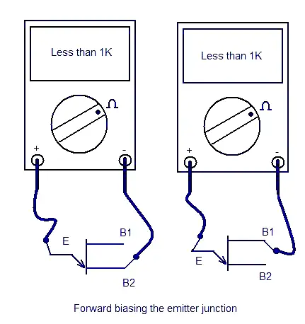
Set the digital multimeter in resistance mode.Connect the positive lead to the emitter and negative lead to B1.The multimeter will show a low resistance (around few 100 ohms).Now connect the positive lead once again to the emitter and ngative lead to the B2 terminal.Again the multimeter will show a low resistance reading (around few 100 ohms).In both cases the reading will be almost same.This test is almost like forward biasing a diode.

forward-biasing-the-emitter-junction

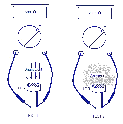
LDR (light dependent resistance) can be very easily tested by using a digital multimeter. We all know that the resistance of an LDR varies according to the light falling on it. At bright light, the LDR resistance will be around 500Ohms and at darkness the resistance will be around 200K. For a proper diagnosis we need to measure the resistance of the LDR at bright light and at darkness.

Test1.
Keep the multimeter at Ohms mode. The LDR must be subjected to a bright light source (day light is enough).Connect the LDR leads to the multimeter terminals as shown in the figure. Now the multimeter will show a low resistance reading around 500 Ohms.

Test2.
Keep the multimeter at Ohms mode. The LDR must be subjected to darkness by covering it with an opaque paper. Connect the LDR leads to the multimeter terminals as shown in the figure. Now the multimeter will show a high resistance reading around 200K.

how-to-test-an-ldr

If both of the above tests are positive then we can conclude that the LDR is healthy.

This article shows you how to test a capacitor using analogue multimeter. Firstly short the capacitor leads for discharging it completely. Set the multimeter to high resistance mode. Connect the multimeter terminals to the capacitor leads. For electrolytic capacitors the positive terminal of multimeter must be connected to the positive lead of the capacitor and negative terminal of multimeter to the negative lead of capacitor. For other capacitor types, polarity is not an issue.

At the moment you connect the multimeter terminals to the capacitor leads, the multimeter needle will move to zero and then slowly move towards infinity and settle there. This will happen only if the capacitor under test is healthy.

  • If the capacitor under test is short, the multimeter needle will go to zero and remain there.
  • If the capacitor under test is open, the multimeter needle will not move (will remain at the infinity position which is the initial position for analogue multi meters).
  • If the capacitor under test has leakage then the needle will first deflect to zero, and then slowly move towards infinity and will settle at a point before infinity.

This is only a rough test and for complete check up you need to varify the capacitor value using a capacitance meter.

Thermistors are of two types, NTC (negative temperature coefficient) and PTC (positive temperature coefficient types). As their name indicates the resistance of an NTC thermistor will decrease with temperature and the resistance of a PTC thermistor will increase with temperature. Both PTC as well as NTC thermistors can be roughly checked by using an analogue multimeter.

Keep the analogue multimeter in resistance mode. Connect the multimeter terminals to the thermistor leads. Polarity is not an issue here. Now heat the thermistor by moving your heated soldering iron tip to it. Now you can see the multimeter reading smoothly increases or decreases depending on whether the thermistor under test is PTC or NTC. This will happen only for a healthy thermistor.

For a faulty thermistor, following observations are possible.

  • The change in reading will not be smooth or there will not be any change.
  • For a short thermistor the meter reading will be always zero.
  • For an open thermistor the meter reading will be always infinity.

This is only a rough test. For a perfect check up; you need some way to measure the temperature and the corresponding resistance reading must be according to the thermistor’s temperature-resistance characteristics provided by the manufacturer.

All the testing methods below uses a multimeter and hence its How to test FET’s especially the JFET and MOSFET using a multimeter.

How to test an FET ?

FET testing method

FET testing method

FETs are checked by measuring different resistances by a multimeter. When resistance is checked between source and drain, it should be of the order of 10 kohms.

How to test a JFET ?

JFET testing methods

JFET testing methods

When a JFET is checked as a diode (gate-to-channel junction) multimeter should indicate low resistance between gate and source with one polarity and very high resistance between gate and source with meter polarity reversed.

Troubleshooting a JFET test

If the meter indicates high resistance with both the polarities, it means that the gate junction is open. On the other hand, if meter indicates low resistance with both polarities, it means that the gate junction is shorted.

How to test a Mosfet ?

Mosfet testing methods

Mosfet testing methods

While checking MOSFET, the resistance measured between gate and drain should be infinitely high in either polarity. Low resistance means faulty device.

Description of Wireless mains voltage tester
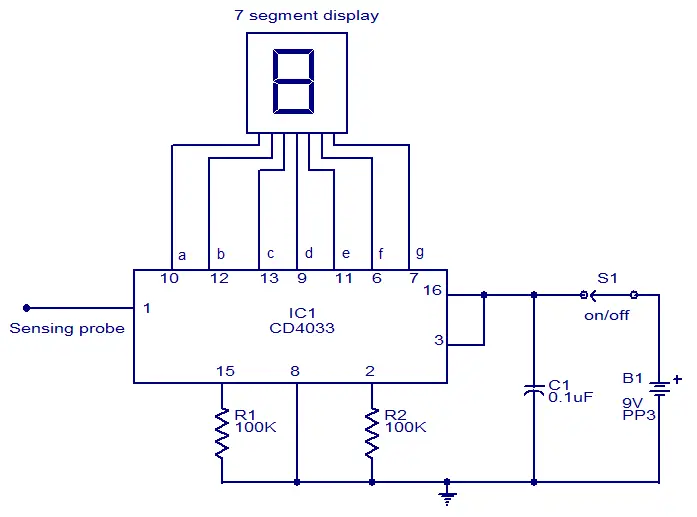
This circuit can be used to test whether mains voltage is present or not without having electric contact with mains line. The CMOS IC CD4033 is the heart of this circuit. The CD4033 consists of a 5 stage decade Johnson counter and an output decoder for converting the Johnson code to a 7 segment decoded output for driving 7 segment LED display. A 10cm long insulated copper wire connected to the clock pin (pin1) of the IC serves as the sensor. The sensor wire has to be placed in the vicinity of the mains wire to be tested. When there is no voltage in the mains line, no voltage will be induced in the sensor wire and the display will show a random digit. When there is voltage in the mains line, a small voltage will be induced in the sensor wire due to electromagnetic induction and this voltage is sufficient enough to clock the CMOS IC CD4033. Now the display will count from zero to nine and repeat.

Circuit diagram.

wireless mains indicator

Notes.

  • The circuit can be assembled on a Vero board.
  • Use 9V PP3 battery for powering the circuit.
  • Use a 10cm insulated wire as the sensor.
  • The IC must be mounted on a holder.
  • Switch S1 can be a miniature ON/OFF switch.