Showing posts with label transmitter circuits. Show all posts
Sunday, November 1, 2009

Simple IR audio link

Description.

Here is a simple IR audio link that can be used to transmit audio signals up to 4 meters. The signal to be transmitted is applied to the base of Q1 via resistor R4.The transistor Q1 drives the IR transmitting diodes D1 and D2.The audio input will be modulated to the IR signals transmitted.
The transmitted IR signals will be picked by the photo transistor Q2.The emitter voltage of the transistor Q2 will change according to the sound modulated to the IR signal. The transistors Q3 and Q4 amplifies this signal to drive the speaker or headphone.C1 and R3 forms a filter to avoid interference from stray IR signals.

Circuit diagram with Parts list.

ir-audio-link-circuit

Notes

The circuit can be assembled on a general purpose PCB.

Use 9V PP3 batteries for powering the transmitter and receiver.

The phototransistor Q2 can be any NPN phototransistor like PNZ154, PNA1605F, BPW77NA or BPW85.

An 8 Ohm speaker or a headphone can be used to hear the sound.

Description of Audio monitoring system
Here is the circuit schematic of a simple audio surveillance system in which the transmitter will pickup sound from one location and the receiver at other location will reproduce it. The receiver and transmitter are connected by only one set of wire. Here both power supply and transmitted signal share the same wire.

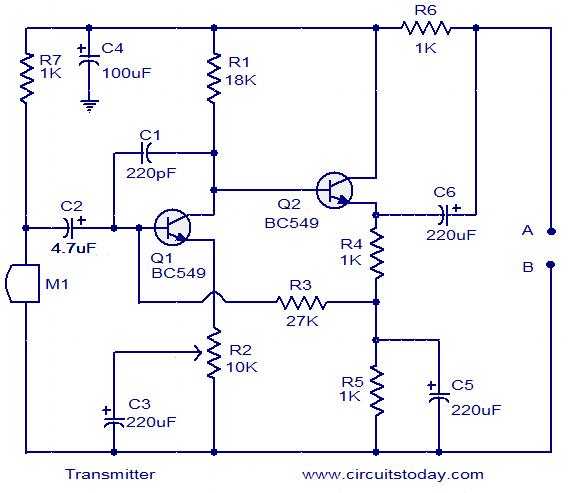
The audio signals picked up by the microphone will be amplified by the double stage amplifier build around transistors Q1 and Q2.The POT R2 controls gain of the amplifier. The power supply for this circuit is drawn from the interconnection lines itself. The capacitor C4 bypasses all audio frequencies & noise from the line and ensures pure DC for the circuit. The output of the amplifier (audio signal) is coupled to the line via the capacitor C6.

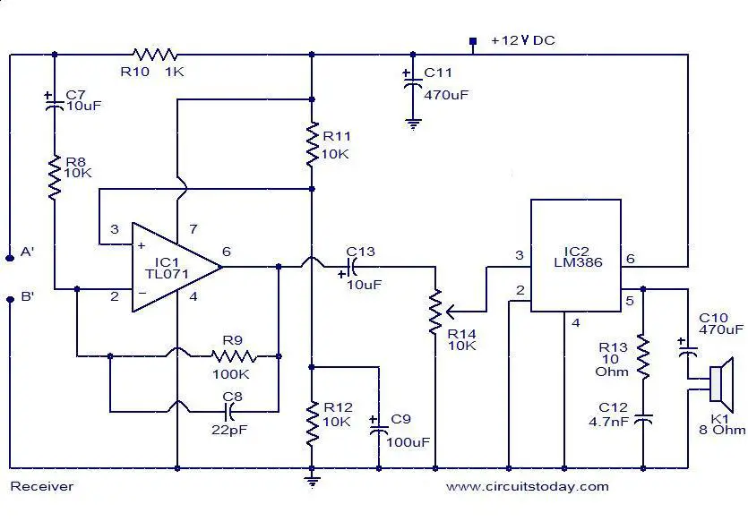
At the receiver end the capacitor C7 extracts the audio signal from the line and feds it to the inverting input of IC1 (TL071) which is wired as a voltage amplifier. Output of IC1 is given to the input of IC2 (LM386) which is a integrated power amplifier.IC2 provided necessary current gain to drive the speaker. The POT R14 can be used control the gain of receiver. Capacitor C11 isolates audio frequencies and noise from the power supply of both the ICs.

Circuit diagram with Parts list.


audio-monitoring-system-receiver

audio-monitoring-system-transmitter

Notes.

  • Assemble the circuit on a general purpose PCB.
  • Terminal A must be connected to A’ using the wire of required length. Do the same with B, B’.
  • The microphone M1 can be a general purpose one.
  • The speaker k1 can be 8 Ohm/2 Watt.
  • POT R2 can be used to control gain of the transmitter.
  • POT R14 can be used to control gain of the receiver.
  • The circuit can be powered from a 12V battery or 12V DC power supply.
  • IC1 and IC2 must be mounted on holders.

Description TV transmitter circuit


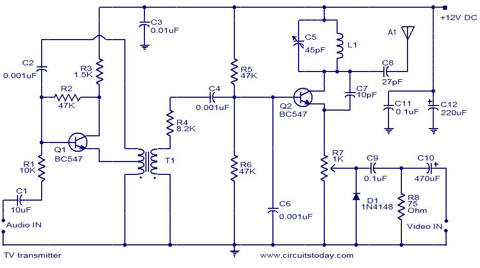
The TV transmitter given here uses UK standard 1 FM modulation for sound and PAL for video modulation. The audio signal to be modulated is pre-amplified using the transistor Q1 and associated components. The transistor Q2 has two jobs: production of carrier frequency and modulation. The pre-amplified audio signal is fed to the base of transistor Q2 for modulation. Capacitor C5 and inductor L1 forms the tank circuit which is responsible for producing the carrier frequency. The video signal is fed to the emitter of transistor Q2 via POT R7 for modulation. The modulated composite signal (audio+video) is transmitted by the antenna A1.

Circuit diagram with Parts list.

tv-transmitter-circuit

Notes.

  • Assemble the circuit on a good quality PCB.
  • Inductor L1 can be made by making 4 turns of 24SWG enameled copper wire on a 6mm dia: plastic former.
  • T1 can be a radio frequency transformer with built in capacitor. (Can be found on old transistor radio boards).
  • Antenna A1 can be a 1M long copper wire. (Experiment with the length to get optimum performance).
  • This transmitter is working in VHF band somewhat between 50 – 210MHz.
  • This transmitter is compatible only with PAL B and PAL G systems.