Showing posts with label ECE mini projects. Show all posts

FREE DOWNLOAD FILES

Physics (Algebra based) Slides

Kinematics

Dynamics

Circular Motion

Work and nergy

Linear Momentum

Temperature

Termodynamics I

Termodynamics II

Electric Charge

Electric Field

Electric Potential

Direct Current Circuits

Magnetism

The Reflection and Refraction of Light

Interference and Diffraction

Physics (HSC Level)

Astrophysics1

Astrophysics2

Compton effect

Cosmic rays

Light Emitting Diodes and Solar Cells
Magnetic force on Moving Charges

Nuclear fusion

Orbital Motion

Photons and Lasers

Transformer

The speed of light


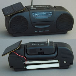
Solar power provides advantages for remote locations where there is a need for power but no electricity available. For example, if you go to the mountains for a camping trip or to the beach for a day in the sun there are no electrical outlets to conveniently plug in to. You might want to use something as simple as a radio that runs on dc power and you can use solar power for this application since a solar panel supplies dc electrical current. Mini radios, as that shown in the photo run on batteries so are easily converted to a solar radio.


Batteries will work for a day or so but if you need to use the radio for many days you would have to carry a lot of batteries with you and the cost can be very high. Also, there are people that live in areas where power is never available and they do not have an endless supply of batteries. For people that want to run a laptop computer there are commercial laptop solar panels that can be used to run the laptop or charge the computer battery.

Science Fair Project Idea/ Objective:

This is a simple idea that can be added to your science fair project to help demonstrate applications of solar energy. You can also use this solar powered radio as an additional demonstration and test for the science fair topics on Amount of Light that Hits a Solar Panel, Angle of Light that Hits a Solar Panel, Wavelength of Light that Hits a Solar Panel and Concentration of Light on a Solar Panel.

Tip:

You will need to match the amount of power delivered by your solar panel to the amount of power required by the radio. In the above picture we used a solar panel that was rated for 4.5 volts and 100 mAmps and a radio that used 4 AA batteries at 1.5 volts each and rated for 6 DC volts. We tried 2 different makes of radio rated at 6 DC volts and both worked well. You can find these types of radios for less than $10 in chain pharmacy's and discount stores. You might have to get one and just try it with a closley matched solar panel.

Materials:

  1. Solar Panel
  2. Battery powered radio (6 volt) or one that works on 4 AA batteries

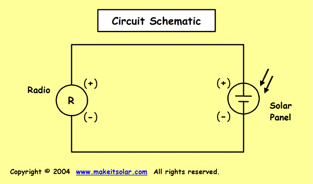
Schematic: (large image)

Solar panel and radio schematic for solar powered radio


What to Do:

On this project you will have to do a little discovery on your own depending on the type of radio you find and the solar panel you are using.
In general, you will have to open the radio and figure out how the wiring is configured. In some cases it will be easy if there is one positive lead and one negative lead. The second radio that we converted to a solar radio was a little more complex but we were still able to fairly easily once we understood the wiring.

The Second Project:

This is a photo of the second solar radio we made. We took the picture indoors and you can see that internal lights were enough to power the digital clock. We have panels that will power up the radio using just a 60 Watt light bulb.


A solar panel needs direct sunlight in order to work best.  When clouds or trees block the sun, the solar panel generates less power than if it had full sunlight. When engineers design solar powered homes or applications they know it is important to install a solar panel in a location that will get the most direct sunlight.

If you are under 18 years old, get permission from an adult to do this experiment.

Science Fair Project Idea/ Objective:

Demonstrate how the power from a solar panel can change as the amount of light changes. You will develop this idea by measuring the amperage output of the solar panel for different light bulb outputs.

Tip:

Light output is listed on the bulb packages in terms of "Lumens". Lumens is not the same as Watts. Watts is the energy used. However, the lumens will generally increase with watts. For a consistent test you should choose all light bulbs from the same manufacturer.

Hypothesis:

A solar panel will deliver more power as it is exposed to increasing amounts of light.

Materials: 

  1. Solar Panel
  2. 4 light bulbs with different light outputs. Different lumens values.
  3. Lamp for the light bulbs
  4. Multi-meter to measure Milli-Amps.
  5. Graph paper and pencil

Schematic: (large image)


Solar panel and meter schematic for amperage measurements

Set Up:

  1. Connect the ammeter to the solar panel and set the solar panel on a flat surface. Set the ammeter output so that it will read milli-amps (mA).
  2. Set up your lamp so that light will shine directly onto the solar panel.
  3. Be sure you will get a reading when you use the bulb with the lowest lumens. You may have to adjust the distance between the lamp and the solar panel.

Procedure

  1. Print out this work sheet or make your own.

  2. Test 3 of the light bulbs with lumens values that are highest, lowest and 1 in-between.
    • Put the bulb in the lamp.
    • Turn on the lamp.
    • Record the mA reading of your multi-meter.

  3. Graph your data for the 3 bulbs for mAmps (Y-axis) as a function of lumens (X-axis).
  4. Draw a line that will connect the 3 data points.
  5. Look at the line on your graph and predict the mA value of the remaining light bulb.
  6. Test the remaining light bulb and add that data point to your graph.

Expected Results:

The line will be fairly straight so you should be able to accurately predict the mAmp readings of other light bulbs based on the light output (lumens).

Try This:

  1. Try taking measurements outside in the Sun. Try it with and without clouds. Try it on a day that is partially cloudy and watch the change of your meter as the clouds move in and out of the path of the sunlight.
  2. You can find light bulbs rated at the same watts from different manufacturers that give off different amounts of lumens. Get 1 or 2 more light bulbs from different manufacturers that have the same watt rating but different lumens ratings. Use your graph to predict the mAmp output of your solar panel for these bulbs. Test the bulbs. How was your prediction? Why?


22 Radio and Receiver Projects for the Evil Genius
2008 - 299 Pages - PDF - 5.81 MB

22 Radio and Receiver Projects for the Evil Genius features a unique collection of projects that teach you radio and electronics essentials such as the radio spectrum, how to read schematics, and how to solder. After each project is completed, you can enjoy listening to and using their new receiver.* Projects include: FM radios, aircraft radios,VHF ham radio receivers,VHF public service radio, old-time radio tubes, shortwave receivers, and free energy receivers* Covers early radio models such as crystal radio as well as more contemporary options* Appeals to skill levels from novice to advanced


ABSTRACT: With advancement in technology and science electronics have been getting smaller and smaller , which enables researchers and scientist to weave the electronics and interconnections into the fabrics. This new technology enables to establish a new concept called electronics textiles (e-textiles) which allows cost-effective and efficient solutions for various application.
In this project, the main idea is monitoring vital body signs by placing the electronics device into a garment in a compact way. Among many vital body signs, poture, respiration rate and body activities like walking running have been monitored. The measurements have been performed with a mems based technology. The electronic components have been placed in to the fabric to form the arf-shirt TO MONITOR BODY SIGNS. COLLECTED DATA FROM VARIOUS SUBJECTS WITH ARF–Shirt system have been transmitted by rf transmission and monitored in real-time.

IMPLEMENTATION: The system contains mainly two parts. One of them is the mobile part on the ARF-Shirt, which contains Microelectronics acceleration, battery based system with miniature RF transmitter, A special type of software is implemented to save battery consumption and makes system more intelligent. The second and the fixed part contains ARX receiver with multiple reader, SC – 2075 connector block, data acquisition board a a computer with a processor software.

ABSTRACT: Issuing season ticket, one time usage ticket, or any kind of ticket which need to issue daily become a massive process which require man power and assistance. The smart card ticketing is an alternative solution for this massive process. The electronic ticket or E-Ticket described here is the new approach to replace the traditional ticketing system. The main advantage of wireless smart card based ticket is, that it can be used repeatedly as per the charging. The ticket can be issue such as one time use, one-day use or even one month or so.
The electronic ticket card is programmed for specific usage period. It can be used as regular traveling ticket where it access with existing ticket machine to issue ticket. The RFID based ticket is an electronic solution for getting / issuing tickets in a busy line. The printing machine attached to the base reader unit will issue the printed form of ticket to the user. Once the card is used, the card is updated with time, usage, ID etc. If it is one-day useable card, the card will lock automatically after one use. The central monitor station can monitor the usage of each card on time. The main advantage of such RFID based cards is , it can be charges by the user with an automatic charger unit with appropriate usage points such as one time , multiple use etc.
The ticket options available as:
• Carnet.
• Period pass ( day, week, month…)
• Tourist / visitor pass (could be distributed in advance, or by hotels)
• Conference delegate pass.
• hop on hop off.
• Multiple product (single or multiple)

The tickets can be used : DATA OPTIONS.
• Value.
• Number of rides.
• Time based.
• Area/zone validity.
• Specific journey.
• Entitlement.

Implementation: The ticket has active super RFID with data storage, printed antenna, battery. The super active two way RFID equipped in the ticket is capable to receive data and transfer updated data to the reader. The reader has active RFID with processor and other interface unit to external gadgets such as printer, keyboard, PC, etc. The recharge point has PC, MCU , and RF units. The command transported from the PC is read and store in the ticket. On every usages the up dated data also stored in the ticket. After the specific usages, the user can re-charge the ticket it the charger point.
In the system one ticket, one base reader with PC interface is provided additional reader can be added as per choice.

ABSTRACT: Radio Frequency identification technology has become an important driver in the modern production logistics activities of today’s information-based industries and economics. With the modern development and latest technology, companies focus more on how these technologies can be implemented and promoted in order to improve their value-added process.
In this project presents one such practical implementation approach for the monitoring and analysis of a discrete manufacturing environment using the super RFID technology. Monitoring the parts flows in manufacturing system time-wise and location-wise is very critical for productivity, cost, quality, inventory, and speed. In companies when the production automation has been implemented the parts are monitored by the system. This may allow better monitoring of the manufacturing process with expedient material flow and more effective planning and control.
This super RFID based manufacturing monitoring and analysis system to monitor where and when a part is located throughout its flow in a production process using RFID tag placed on the parts and antennas located at appropriate places. The system will enable the visibility of multiple parts simultaneously without requiring operator support and collect the following information related to a part.
1. Arrival time to a workstation.
2. Activity start time.
3. Activity end time.
4. Departure time from the workstation.
5. Location of a part.

Implementation.
In this system every parts in the production is equipped with a super RFID tag. The manufacturing plant is installed with reader antenna at appropriate locations. The data from the part/tag is read on real time. The reader can receive data from many tags at a time. The location information and other data is processed in the base reader unit and feed in to a PC. The final display is shown in the PC using software.
Hardware involved. : Super compact active RFID tag (as per monitoring parts required) Directional antenna, Reader base unit, Interface adaptor, PC software.

· Snow Shoveling Robot Presentation Slides - Report

· The Future Soldier System Presentation Slides - Report

· Wire Routing Tool Presentation Slides - Report

· Detachable Pothole Detection and Warning System Presentation Slides - Report

· Flipper The Persistent Vehicle Presentation Slides - Report

· Autonomous Ground Vehicle Presentation Slides - Report

· In-Pipe Ispection Robot Presentation Slides - Report

· Windbot Presentation Slides - Report

· The Ground Sailor Presentation Slides - Report

· The Worksite Leveler Robot Report

· Automation of Fiber Composite Manufacturing Process Presentation Slides - Report

· Multi-Vehicles Formation Control Exploring A Scalar Field Presentation Slides - Report

· Boiler Room Monitoring System Presentation Slides - Report

· Motion Control System using DC Motor Presentation Slides - Report

· Coal Mine Fire Detection System Presentation Slides - Report

· Autonomous Sprinkler System with Object Avoidance Presentation Slides - Report

· Property Protecting Turret Presentation Slides - Report

· Ultrasonic 3D Radar Presentation Slides - Report