Showing posts with label sensor circuits. Show all posts
Monday, October 12, 2009

Single chip metal detector circuit

Description.
This is a simple single chip metal detector circuit based on IC CS209A from the Cherry Semiconductors. A 100uH coil is used to sense the presence of metal. The IC CS209A has a built in oscillator circuit and the coil L1 forms a part of its external LC circuit which determines the frequency of oscillation. The inductance of the coil change in the presence of metals and the resultant change in oscillation is demodulated to create an alarm. The LED gives a visual indication too. This circuit can sense metals up to a distance of few inches.

Circuit diagram with Parts list.

single-chip-metal-detector-circuit

Notes.

  • Assemble the circuit on a general purpose PCB.
  • The switch S1 can be a slide type ON/OFF switch.
  • The IC must be mounted on a holder.
  • The POT R1 can be used to adjust the sensitivity of the circuit.

Notes.

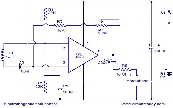
This is a very simple circuit that can be used to sense electromagnetic radiations. The circuit can even detect hidden wrings. A 1mH inductor is used for sensing the electric field. The electric field will induce a small voltage in the sensor inductor and this induced voltage is amplified by the opamp.The headphone connect at the output of the opamp will give an audio indication of the electric field. For example, the electric field around a mains transformer can be heard as a 50 Hz hum. The POT R4 can be used to adjust the gain of the amplifier. By keeping the sensor inductor near to a telephone line, you can even hear the telephone conversations.

Circuit diagram with Parts list.

electromagnetic-field-sensor-circuit

Notes.

  • Assemble the circuit on a general purpose PCB.
  • The circuit can be powered from a 9V PP3 battery.
  • It is better to have a radial type inductor for L1.
  • The POT R4 can be used to adjust the gain.
  • The switch S1 can be a slide type ON/OFF switch.
  • The IC1 must be mounted on a holder.
  • All electrolytic capacitors must be rated at least 15V.

Description.
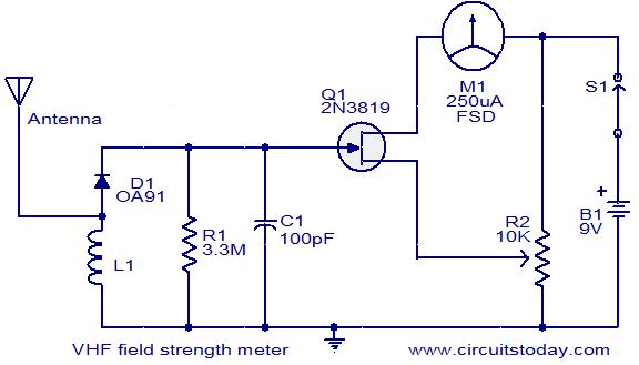
This is a simple and low cost wide band VHF field strength meter. The field strength is measured by converting the radio signal to DC and measuring it. The RF signal will be picked up by the coil and rectified by the diode D1.Even a very small DC voltage is sufficient to alter the biasing of FET and it will be reflected in the meter as an indication of the presence of a radio signal. The meter can be calibrated by adjusting the preset R2 to make meter M1 read ZERO in the absence of any radio signal. This circuit is not very sensitive, but can sense radio signals from hand held FM transmitters up to a distance of few meters( ideal for theoretical demonstrations).

Circuit diagram with Parts list.

vhf-field-strength-meter

Notes.

  • The circuit can be assembled on a general purpose PCB.
  • Use a 9V PP3 battery for powering the circuit.
  • Use a 250uA FSD current meter for M1.Using a lower FSD meter will improve sensitivity.
  • The coil L1 can be made by making 6 turns of 20 SWG enameled copper wire on a ¼ inch plastic former.
  • The antenna can be a telescopic whip antenna.

Description.

This simple circuit will produce an alarm whenever the temperature falls below zero degree. A thermistor is used here to sense temperature. The op-amp LM7215 is used to compare the reference voltage and voltage from the thermistor network. Reference voltage is given to the non inverting input (pin3) of the IC and voltage from thermistor network is given to the inverting input (pin4).When temperature becomes less than zero degree the voltage at the non inverting input becomes larger than the voltage at the inverting input and the output of the op-amp becomes high. This makes the transistor Q1 ON and drives the piezo buzzer to make the alarm. In the power supply section, IC 7805 is used to derive 5V from the 9V battery.

Circuit diagram with Parts list.

zero-degree-alarm-circuit

Power supply for this circuit.

power-supply

Notes.

  • Assemble the circuit on a good quality PCB.
  • The thermistor used here is a glass bead thermistor, type No: KEYSTONE RL0503-5536K-122-MS (361K @ 0 degree Celsius and 100K @ 25 degree Celsius).
  • The IC1 must be mounted on a holder.
  • The battery B1 can be a 9V PP3 battery.

Description.
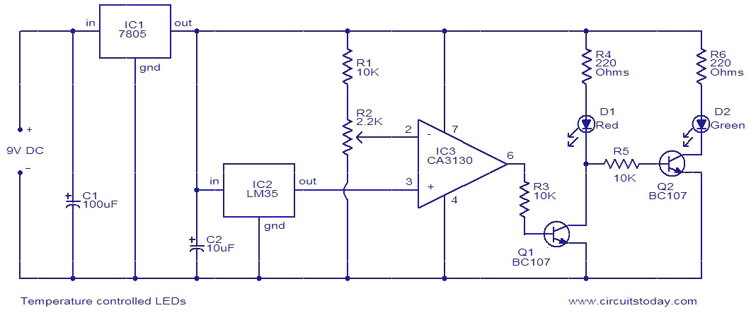
The circuit is nothing but two LEDs (D1 and D2), whose status are controlled by the temperature of the surroundings. The famous IC LM35 is used as the temperature sensor here. Output of LM35 increases by 10mV per degree rise in temperature. Output of LM35 is connected to the non inverting input of the opamp CA3130.The inverting input of the same opamp can be given with the required reference voltage using POT R2. If the reference voltage is 0.8V, then the voltage at the non inverting input (output of LM35) becomes 0.8V when the temperature is 80 degree Celsius. At this point the output of IC3 goes to positive saturation. This makes the transistor Q1 On and LED D1 glows. Since the base of Q2 is connected to the collector of Q1, Q2 will be switched OFF and LED D2 remains OFF. When the temperature is below 80 degree Celsius the reverse happens.IC1 produces a stable 5V DC working voltage from the available9V DC supply. If you already have a 5V DC supply then you can use it directly.

Circuit diagram.

temperature-controlled-leds

Notes.

  • The circuit can be assembled on a Vero board.
  • IC3 must be mounted on a holder.
  • The temperature trip point can be set by adjusting POTR2.
  • Type no of Q1 and Q2 are not very critical. Any general purpose NPN transistors will do it.