Showing posts with label AUDIO circuits. Show all posts
Sunday, November 1, 2009

Touch Switch Circuit using NE 555

Description

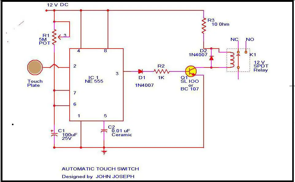
This is the circuit diagram of a small touch plate controller using IC NE 555 .This circuit is ideally useful for making touch operated doorbells, buzzers,toys etc which when touched on the touch plate operates the relay for a preset time and the turns off automatically.

This circuit is realized by utilizing the high input impedance of trigger pin of the 555 IC.When the IC is triggered by the induced voltage of human body the output goes high for a time determined by R1 and C1.The transistor is used to drive the relay.The relay contacts can be used to drive the load like bell, motor , lights etc.

Notes.

To make the touch plate cut a 1 sqcm thin metal sheet.

To setup the circuit connect to power supply and adjust R1 while keeping touching on the touch plate.Stop at the point where relay activates.If relay is in the activated state initially then do the same until the relay is deactivated.

Circuit Diagram & Parts List .Click Here.
touch-plate.JPG

Description.

When S2 is ON ,the circuit here operates as an astable multi vibrator and the LED is lit for about o.1sec,flasing every 1.5 seconds.Since the human reaction time is more than this,you cannot catch it once it is seen o,by pressing S1.If your sense of time interval is good,and you press S1 with in that 0.1 sec,the discharging of C1 stops and then the lamp stays lit.you may change the ON and OFF periods by changing R1 and R2 or C1 to suit your convenience.

Circuit diagram with Parts list.

sense-of-time-tester-circuit.JPG

Notes.

  • Switch S1 can be a pushbutton switch.
  • Switch S2 can be a SPST switch.
  • The circuit can be powered from a 9V battery or 9V DC power supply.

Description.

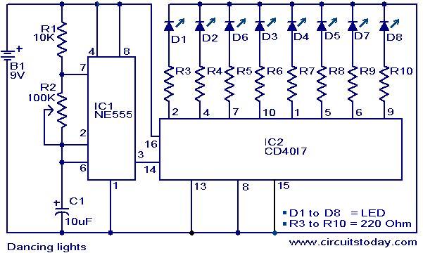
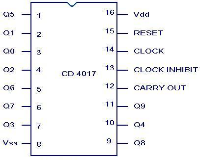
Here is a simple dancing light circuit based on NE555 (IC1) & CD4017 (IC2) .The IC1 is wired as an astable multivibrator to provide the clock pulses for the CD4017.For each clock pulse receiving at the clock input (pin14) of IC CD4017, the outputs Q0 to Q9 (refer pin diagram of CD 401) becomes high one by one alternatively.The LEDs connected to these pins glow in the same fashion to give a dancing effect.The speed of the dancing LEDs depend on the frequency of the clock pulses generated by the IC1.

Circuit diagram with Parts list.

dancing-_light-circuit.JPG

Notes.

  • Assemble the circuit on a good quality PCB or common board.
  • The ICs must be mounted on holders.
  • The speed of the dancing LEDs can be adjusted by varying POT R2.
  • The capacitor C1 must be rated 15V.
  • Using different color LEDs could produce a better visual effect.

CD 4017 Pin configuration.

cd-4017-_pinout.JPG

Description.

The circuit given here can be used for tossing head or tail. There are many games in which a tossing is required to start and this circuit can be used in all such instances.

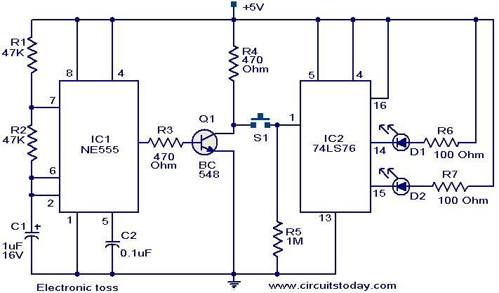
The circuit uses two ICs NE 555 timer (IC1) and 74LS76 dual JK flip flop (IC2).The IC 1 is wired as an astable multi vibrator operating at 10Hz.The output of IC1 is inverted by using the transistor Q1.The collector of Q1 is connected to the pin 1 of IC2 via the push button switch S1.The IC2 is wired in toggle mode. When push button S1 is pressed the output pins 14 and 15 of IC2 starts toggling in state. The LEDs connected to these pins also toggles (Since the frequency of toggling is 10Hz, we feel both LEDs glowing).When push button S1 is released either one of the LED remains ON indicating the head or tail.

Circuit diagram with Parts list.

electronic-toss-circuit.JPG

Notes.

  • The circuit can be powered from 5 V DC.
  • Switch S1 is a push button switch.
  • The ICs must be mounted on holders.
  • The circuit can be assembled on a general purpose PCB.

Description.
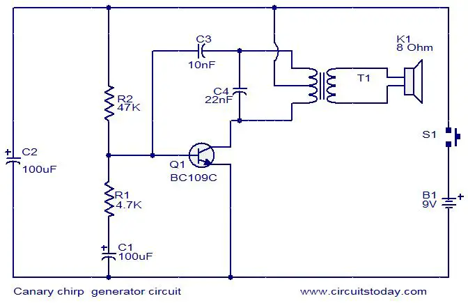
This is a simple electronic alarm circuit that imitates the chirping of a canary. The circuit is nothing but a Hartley oscillator with few more passive components added. As the capacitor C1 charges through the resistor R1 and the transistor Q1 is driven to cut off. This makes the oscillations to stop. As the capacitor discharges through the Resistor R1 and base emitter junction of the transistor the oscillation start again. Actually the R1 and C1 are the components that make the characteristic chirping sound.

Circuit diagram with Parts list.

canary-chirping-generator-circuit

Notes.

  • Assemble the circuit on a general purpose PCB.
  • The circuit can be powered from a 9V PP3 battery.
  • The transformer T1 can be a audio output transformer like LT700.
  • If LT700 is not available, try the audio output transformer used on you old transistor radio board.
  • The speaker can be an 8 ohm tweeter.
  • Switch S1 can be a push button switch.
  • The chirping sound can be altered by changing the value of R1 and C1.

Description.

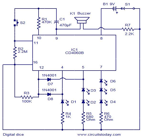
This is a simple and easy to construct digital dice circuit. The circuit is based on a single IC, CD4060B.The dice consists of six LEDs marked D1 to D6.The number of LEDs glowing indicates the numeral.

The heart of this circuit is 14 stage binary ripple counter IC CD4060B.The IC also has a built-in oscillator. The oscillator output (here 2 KHz) is used to clock the binary ripple counter. The counter increments by one in its natural count sequence each time it is clocked. The oscillator in initially inhibited as long as the pushbutton switch S2 is not pressed. The counter outputs will be in logic zero state and all the six LEDs will be ON.As the push button S2 is pressed, oscillator is enabled and the counter starts counting. The counter outputs (pin 4, 5 & 7) changes from 000 to 101 and then resets to 000 to repeat the sequence. After 101 the counter does not advances to 110 because of R3, D7 & D8.When the counter just advances from 101 to 110 the diodes D7 & D8 become reverse biased and makes the reset pin (pin 12) high to reset the counter.

The counter counts as long as the push button switch S2 is pressed. Also the micro buzzer will sound as long as the IC is counting. When the push button switch S2 is released, the counting is stopped and holds the existing state to represent the random number.

Circuit diagram with Parts list.
digital-dice-circuit

Notes.

  • Switch S1 is the ON/OFF switch.
  • Switch S2 can be a push button switch.
  • Buzzer K1 is a piezo buzzer.
  • The circuit can be powered from a 9V PP3 battery.
  • The IC must be mounted on a holder.

Description.
This simple circuit produces a beeping sound that lasts for around 3 seconds whenever you make a whistle. The CMOS Hex inverter CD4049 is the heart of this circuit. Out of the six inverters in CD4049, U1a is wired as an audio amplifier which amplifies the signal picked up by the microphone M1.The U1b is wired as a band pass filter with center frequency around 2KHz.The filter is necessary in order to pass the frequency corresponding to whistling sound and suppress all other frequencies .If the filter is not there, the circuit could easily get false triggered.U1d is wired as a 3S delay monostable multivibrator.The output U1d drives the astable multivibrator formed by U1e and U1f.The astable multivibrator is operating around 4Hz.The combined effect is a intermittent beeping sound that lasts for around 3S.Transistor Q1 is used to drive the buzzer B1.

Circuit diagram with Parts list.

whisle-to-beep-circuit

Notes.

  • Assemble the circuit on a good quality PCB.
  • The circuit can be powered from a 3V battery.
  • IC U1 is a CMOS CD4049 Hex inverter.
  • M1 can be an electret microphone.
  • B1 can be a 3V piezo buzzer.
  • Mount the IC on a holder.
  • The duration of beeping can be adjusted by varying the components C4 and R9.

Description.
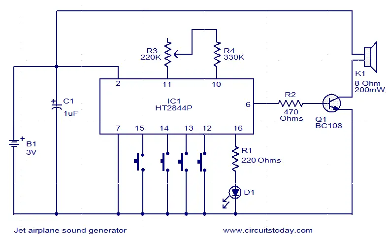
This jet engine sound generator circuit is based on the sound generator IC HT2844P from Holtek Semiconductors. This particular IC can make four sounds namely low speed sound of jet engine, high speed sound of jet engine, missile sound and machine gun sound. Each of these sounds can be activated by connecting the pins 12, 13, 14and 15 to ground by using the respective push button switches. Resistor R3 can be used for manually increasing or decreasing the speed.LED D1 gives a visible indication of the sound.

Circuit diagram.

jet-engine-sound-generator

Notes.

  • The circuit can be powered from a 3V battery.
  • Do not give more than 3.3V to the IC.
  • K1 can be a 200mW/8 Ohm speaker.
  • IC1 must be mounted on a holder.

Description.
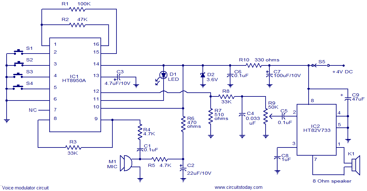
This is a very versatile voice modulator circuit using IC HT8950A from Holtek Semiconductors. The IC is capable of creating 7 upward or downward steps on the frequency of the input voice at a rate of 8Hz. There is also two special variation effects namely Vibrato mode and Robot mode. This circuit finds a lot of application in systems like telephone, speech processors, toys, mixers etc. A microphone is used to pick up the input voice. Push button switches S2 and S3 can be used for the upward and downward frequency stepping .Push button switch S1 can be used to activate Vibrato mode and push button switch S4 can be used to activate the Robot mode. IC HT82V733 (also from Holtek) is used to amplify the output of the voice modulator.LED D1 indicates the voice level.

Circuit diagram.

voice modulator circuit

Notes.

  • The circuit can be assembled on a Vero board.
  • Do not give more than 4.5v to the circuit.
  • Switches S1 to S4 can be miniature push button switches.
  • S5 can be a miniature ON/OFF switch.
  • K1 can be an 8 ohm speaker.
  • IC1 and IC2 must be mounted on holders.