Showing posts with label Telephone circuits. Show all posts
Sunday, November 1, 2009

circuit for Telephone off-hook indicator

Description.

The circuit depicted here can be used as an indicator when the telephone receiver is off-hook. The circuit can be in corporated with old telephones that does not have such an indicator.

The circuit uses a complementary darling to pair using Q1 (2N3904)and Q2 (2n3906) to sense whether the receiver is off hook and glows a LED to show the condition.

Circuit diagram with Parts list.
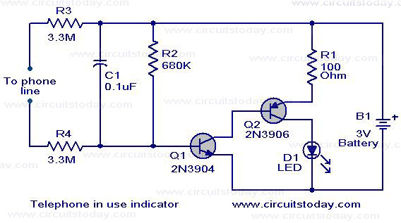
telephone-in-use-indicator-circuit.JPG

Notes.

  • The LED must glow when the circuit is not connected to the telephone line as well as when the telephone is off-hook.
  • If the LED does not go OFF when the receiver is restored on hook change the value of R2 so that about 3.5 V comes across it.
  • The circuit can be powered from a 3V battery.

Description.

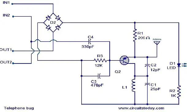
A simple telephone transmitter circuit that is ideal for transmitting the telephone conversation through small distances.The circuit is very simple and uses only few components.The entire circuit can be easily included in the telephone itself or in the junction box.The circuit is powered from the telephone line itself.

The transistor Q2 is wired as a a Colpitts oscillator to produce oscillations in the FM transmission band.The audio signal from the telephone line is coupled to the the base of Q2 to obtain the frequency modulation.The LED D1 acts as a power on indicator.

Circuit diagram with Parts list.

telephone_-bug-circuit.JPG

Notes.

  • Any radio frequency PNP transistor like A933 can be used for Q2.
  • For L1 make 8 turns of 0 .6mm dia enameled copper wire on a 3.6mm dia steel bolt.
  • For antenna use a 15cm long 0.6 mm dia copper wire.

Description.

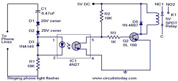
This circuit can be used to glow a bulb or turn a alarm when the phone rings.Using this circuit nuissence of telephone ring at night can be avoided.

When the telephone rings the line voltage rises to 72 volts.At this time the LED in the opto-coupler glows and the transistor conducts. Due to this the transistor Q1 conducts.This makes the relay ON.The load connected to the relay whether bulb or bell turns ON.

Circuit diagram with Parts list.

ringing-phone-flasher-circuit1.jpg

Notes.

  • Assemble the circuit diagram on a good quality PCB or common board.
  • Use a 5V DC power supply for powering the circuit.
  • The load can be connected through NC1,NC2 & C points of the relay.

Description.

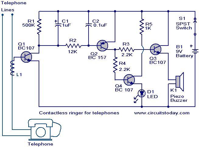
The contact less telephone ringer circuit can produce a ring as well as a visual indication when a call comes.The main advantage is that since there is no direct contact between the phone line and the circuit there is no chance for a loading or disturbance in the telephone line.

When the telephone rings 60 Hz AC signal is generated which produces a proportional magnetic field around the telephone lines.These magnetic field will be picked up by the coil L1 due to electromagnetic induction.A proportional voltage is developed across L1 and it will bias transistor Q1 to ON.This results in the conduction of transistors Q2,Q3 andQ4.The buzzer will ring and the LED will glow.The switch S1 acts as an ON/OFF switch.

Circuit diagram with Parts List.

contactless-telephone-ringer_circuit.JPG

Notes.

  • For L1 make 50 close turns of 28 SWG enameled copper wire on any of the two telephone wires.Connect one end of the coil to base of Q1 and leave other end free.
  • If the circuit not works by try by changing the end of the L1 connected to base of Q1.
  • A 9V transistor radio battery can be used as the power source.
  • Assemble the circuit on a good quality PCB or common board.
  • Use of this type or any other devices other than the allowed telephones and devices with the telephone line may be a law violation in some nations.Check it properly before trying.

Description.

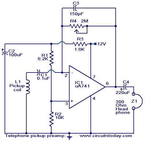
Here is a simple circuit based on IC uA 741 that can be used to pickup voice from telephone lines without even contacting the line. If a high impedance magnetic core is placed near a telephone instrument or near one of the telephone wires, it picks up inductively both sides of the telephonic conversation without any electrical contact. A preamplifier based on IC uA741 is used to pickup these signals. The circuit is nothing but an inverting amplifier whose gain depends on the feedback resistance R4.The Op-Amp produces the necessary gain to drive the headphone. The circuit can be used as a telephone bug too.

Circuit diagram with Parts list.

telephone-pickup-preamplifer-circuit.JPG

Notes.

  • Assemble the circuit on a good quality PCB or common board.
  • You can use 9 to 24 V DC for powering the circuit.I prefer 12V.
  • The coil L1 can be made by winding 3000 turns of 0.4mm insulated copper wire on a plastic former.
  • If the pickup is bad increase the no of turns to 5000 and try.
  • The POT R4 can be used for gain adjustments.

Description.

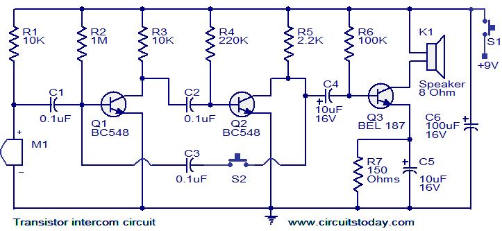
Here is a simple but effective intercom circuit that is based fully on transistors.The circuit is based on a three stage RC coupled amplifier. When the pushbutton S2 is pressed, the amplifier circuit wired around T1 & T2 becomes an astable multivibrator and starts producing the ringing signals. These ringing signals will be amplified by the transistor T3 to drive the speaker. When the push button S2 is released the circuit will behave as an ordinary amplifier and you can talk to the other side through it.

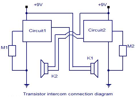
To construct a two way intercom, make two identical copies of the circuit given below and connect it according to the given connection diagram. The stand by current consumption of this circuit is around 20mA.

Circuit diagram with Parts list.

transistor-intercom-circuit.jpg

Connection diagram.

transistor-intercom-connection-diagram.jpg

Notes.

  • Assemble the circuit on a good quality PCB.
  • Use 9V PP3 battery for powering the circuit.
  • The Mic M1 can be condenser micro phone.
  • Use push to ON type push button switch for S2.
  • Use a slide switch for switch S1.S1 can be used to power the circuit.

Description.

This is a simple, but very useful circuit that can be used to transmit telephone conversations. When the telephone receiver is on hook the voltage across the lines will be about 48 volts. The preset R7 is so adjusted to obtain a 24.7 V across between the cathode of D2 and ground. At this voltage the Zener diode D2 will be in breakdown and the transistor T1 will conduct. This makes the transistor T2 OFF. When the receiver is off hook, the line voltage drops to about 11 volts. This makes the transistor T1 OFF and subsequently the T2 ON. The T2 in switched ON condition will provide a DC path for the transistor T3 used in the FM transmitter section.

The transistor T3 is wired as a common emitter radio frequency oscillator. In simple words the transistor T2 serves as an ON/OFF switch for this oscillator. The modulated signal will be available at the collector of transistor T3 and the signal id fed to the antenna via capacitor C5.

Circuit diagram with Parts list.

telephone-transmitter-circuit

Notes.

  • Assemble the circuit on a good quality PCB.
  • For L1 make 45 turns of 36 SWG enameled copper wire on the resistor R6 itself.
  • The resistor R6 must be a 1M, 1 watt resistor.
  • For L2 make 3 turns of 21 SWG enameled copper wire on a 12 mm plastic former.
  • For antenna, use a 1 meter insulated copper wire.
  • The capacitor C3 can be a 50pF trimmer.

Description.
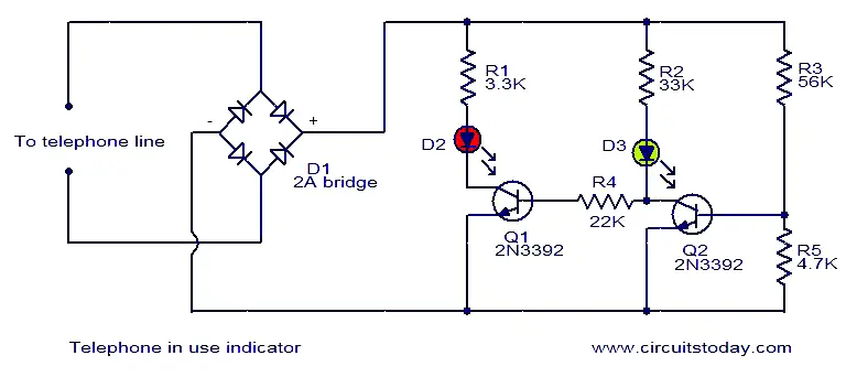
Here is a simple circuit that can be used as a telephone status indicator. When the telephone is in use (off hook) the transistor Q1 switches ON making the red LED D2 glow. When the telephone is not in use (on hook) the Q1 turns OFF and Q2 turns ON. This makes the red LED D2 off and green LED D3 ON. The circuit is powered from the phone line itself and no external power supply is required.

Circuit diagram with Parts list.

telephone-in-use-indicator

Notes.

  • The circuit can be assembled on a general purpose PCB.
  • IF 2A ampere bridge is not available, make one using diodes like 1N4007.
  • Note that some countries prohibit people from connecting other devices to the phone line.