Simple Lamp Dimmer/ Fan Regulator
Description .
This is the circuit diagram of the simplest lamp dimmer or fan regulator.The circuit is based on the principle of power control using a Triac.The circuit works by varying the firing angle of the Triac . Resistors R1 ,R2 and capacitor C2 are associated with this.The firing angle can be varied by varying the value of any of these components.Here R1 is selected as the variable element .By varying the value of R1 the firing angle of Triac changes (in simple words, how much time should Triac conduct) changes.This directly varies the load power, since load is driven by Triac.The firing pulses are given to the gate of Triac T1 using Diac D1.
Notes
Assemble the circuit on a good quality PCB or common board.The load whether lamp ,fan or any thing ,should be less than 200 Watts.To connect higher loads replace the Triac BT 136 with a higher Watt capacity Triac . All parts of the circuit are active with potential shock hazard.So be careful.
I advice to test the circuit with a low voltage supply (say 12V or 24V AC) and a small load (a same volt bulb) ,before connecting the circuit to mains.
Parts List
R1 1o K 1 Watt Resistor
R2 1o0 K Potentiometer (Variable Resistance)
C1 0.1 uF (500V or above ) Polyester Capacitor
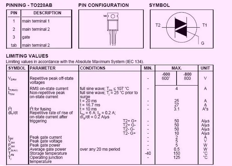
T1 BT 136 Triac
D1 DB2 Diac
Circuit Diagram BT 136Triac Necessary Data.

CLICK THE IMAGES TO ENLARGE
0 comments:
Post a Comment